


Shock metamorphism – shock effects
Terms written in italics are in general explained in the Impact Structure and Meteorite Crater Glossary
Upon collision of a large cosmic projectile (asteroid, comet) with the Earth’s surface shock waves propagating into the impactor and into the underground belong to the most important processes in this geologically prominent event. Impact shock waves are characterized by an instantaneous onset of extreme pressures (up to the order of megabars) and extreme temperatures (up to 10,000 degrees or more) on release of the pressure. These temperatures are enough to more or less completely vaporize the impactor and a volume of the target rocks roughly comparable to the volume of the impactor resulting in a giant expanding impact vapor plume. On propagating roughly hemispherically into the underground target rocks, shock wave energy diminishes and so do pressures and temperatures. Correspondingly, a zone of rock melt follows the vaporized zone, and when shock energy is further lowered rocks will only be heavily damaged (fractured, brecciated) with decreasing intensity.
Shock metamorphism, shock-metamorphic effects or simply shock effects are the terms used to describe modifications in rocks and minerals caused by the passage of shock waves. In the following we will describe the most important effects starting with the highest stages of shock-induced pressures and temperatures.
Shock melt
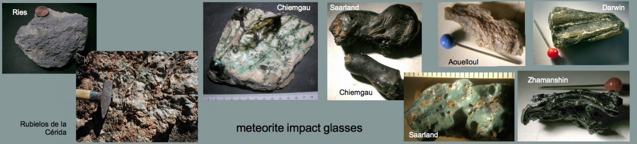
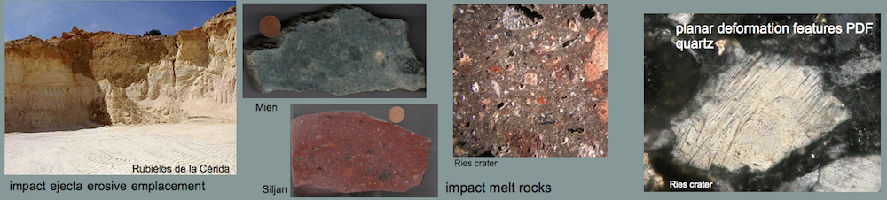
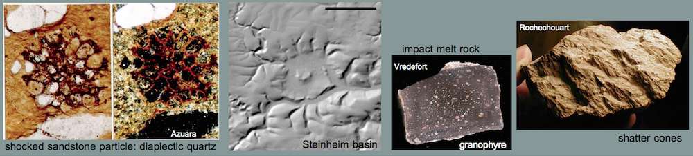
Melt rocks from shock wave passage are formed at pressures of the order of 60 GPa (= 600 kbar) and are frequently found in larger quantities in impact structures in crystalline targets where they may form whole melt rock sheets. These melt rocks may resemble normal magmatic rocks and have been confused with them (e.g., the granophyre from the Vredefort, South Africa, impact structure).
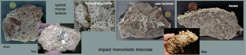
Impact structures in sedimentary targets in general lack massif melt rock occurrence even when silicate rocks contribute to the target stratigraphy. This observation is explained by Kieffer & Simonds (1980) who conclude that the large amount of shock-produced volatiles (from pore water vaporization and limestone decarbonization) in sedimentary targets prevents melt sheet formation and, instead, finely disperses the shock-melted material.
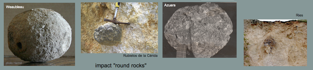
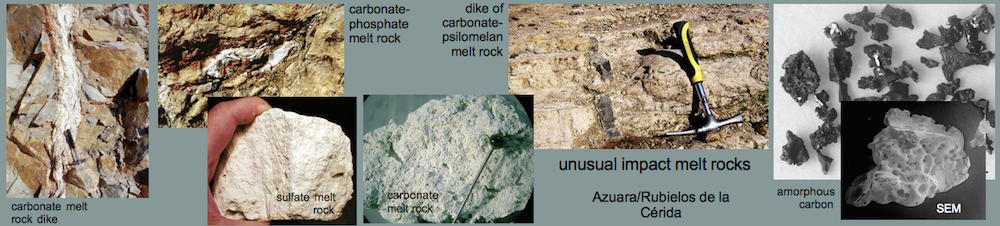
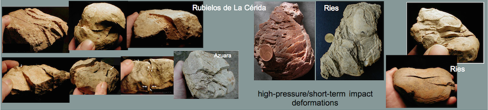
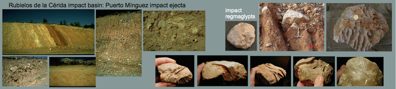
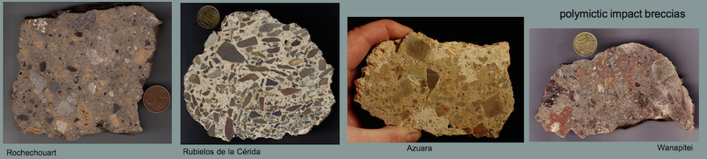
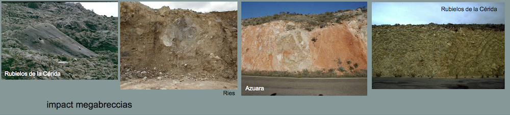
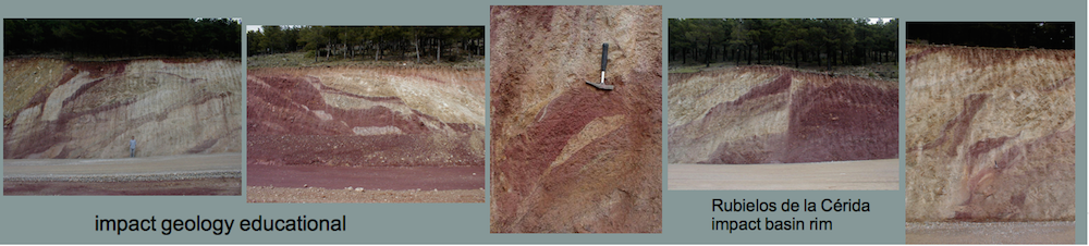
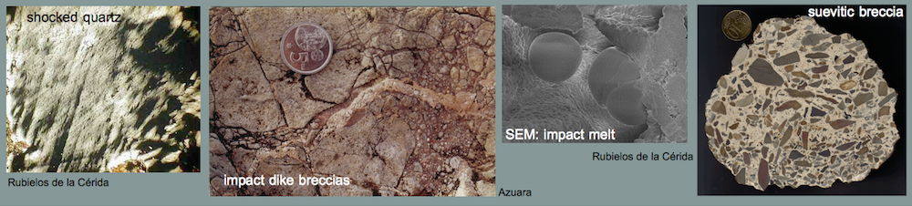
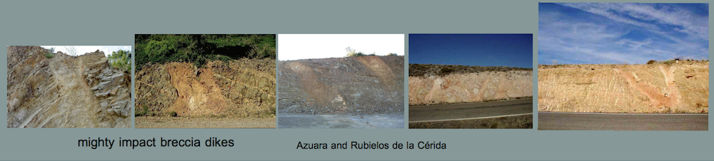
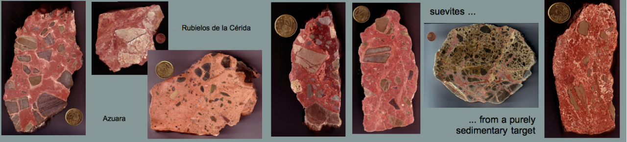
Even stranger shock-metamorphic behavior is found in carbonate targets. Shocked carbonate rocks (limestones, dolomites) may undergo decarbonization but may also melt. Different from silicate rocks, however, carbonate melts cannot be chilled to form glass, but they immediately crystallize to form carbonate again. Hence, shock-produced carbonate melt rocks may exist in impact structures, but on cursory inspection they may elude identification. Impact carbonate melt rocks have been described for the Haughton and Chicxulub impact structures and especially for the large structures of the Azuara – Rubielos de la Cérida (Spain) multiple-impact event. Due to abundant carbonate rocks in the roughly 10 km thick purely sedimentary Azuara – Rubielos de la Cérida target, various carbonate melt rocks play a major role among the impactites exposed over roughly 120 km extent of the impact site (also see here: )
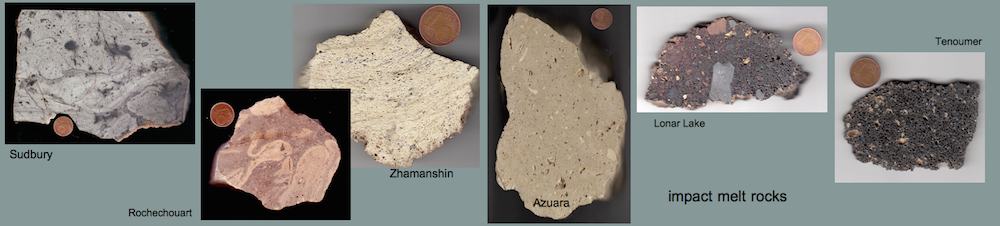
Photos of quite a few macroscopic shock-metamorphic melt rocks from our impact rock collection are shown on the Impact melt page of this website. Here we focus on microscopic observations of shock melt that is commonly found in highly shocked impact breccias (e.g., suevites, suevite breccias).
Silicate melt (Azuara and Rubielos de la Cérida impact structures)
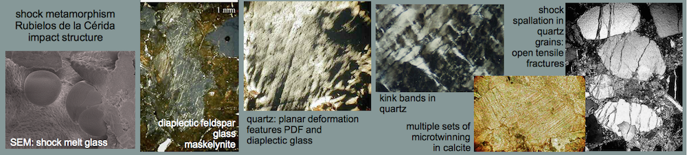
 Fig. 1. Melt glass with vesicles, schlieren and mineral fragments; photomicrograph, plane polarized light and xx nicols. Strongly shocked dike breccia, near Santa Cruz de Nogueras, Azuara impact structure, Spain. The field is 9 mm wide.
 Fig. 2. Partly recrystallized melt glass; photomicrograph, plane polarized light (left) and xx nicols. Strongly shocked dike breccia, near Santa Cruz de Nogueras, Azuara impact structure, Spain. The field is 1 mm wide.

Fig. 3. Quartz grain coated with melt glass. Photomicrographs; crossed nicols (upper left) and plane polarized light. From a strongly shocked polymictic breccia; near Nogueras, Azuara impact structure. The field is 200 µm wide.
 Fig. 4. Shock melt glass particle in carbonate matrix. Suevite basal braccia, Azuara impact structure, Cucalón suevite deposit. Photomicrograph, plane light and crossed polarizers; field width ca. 240 µm.
 Fig. 5. Silicate shock melt rock, > 90% pure glass from melted shale; Barrachina megabreccia, Rubielos de la Cérida impact basin. Optical microscope; field width 15 mm.
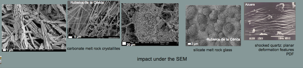
 Fig. 6. SEM image taken from the impact glass in Fig. 5 (shock-melted shale); Rubielos de la Cérida impact basin, Barrachina megabreccia.
Carbonate melt (Azuara and Rubielos de la Cérida impact structures)
 Fig. 7. White relics of carbonate melt coating a disintegrated, decarbonized vesicular limestone. Rubielos de la Cérida impact basin, Spain.

 Fig. 8. SEM image of the relics of carbonate melt; Rubielos de la Cérida impact basin, basin rim between Escorihuela and El Pobo. Note the vesicular felted texture.
 Fig. 9. SEM image of the relics of carbonate melt, formerly probably Muschelkalk limestone. Rubielos de la Cérida impact basin, Spain. Note the dendritic crystallites (field width 25 µm).
Diaplectic glass – quartz, feldspar and muscovite
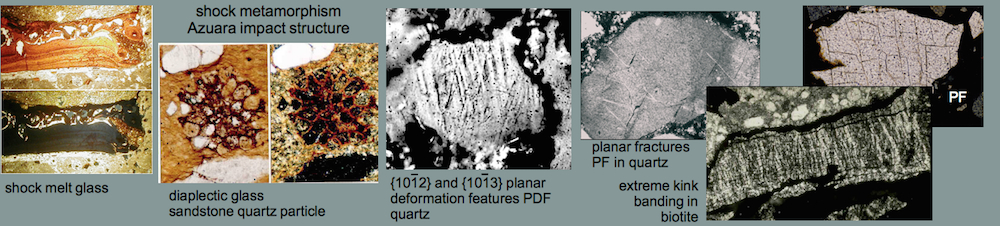
In the 300 – 500 kbar (30 – 50 GPa) shock pressure range, the complete isotropization of quartz and feldspar is typical. In other words, the optically isotropic and x-ray amorphous diaplectic glass is formed by shock damage of a mineral and not by melting. According to current knowledge, diaplectic glass cannot be formed in endogenetic processes. Patchy shock isotropization in quartz starts at about 100 kbar (10 GPa); see image below.
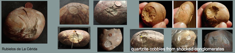
As far as we know, diaplectic micas have hitherto not been described from shocked impactites or from shock experiments. Below we show photomicrographs of an obviously strongly shocked quartzite cobble from the Chiemgau impact (crater #001) exhibiting diaplectic muscovite in combination with diaplectic feldspar glass.
Diaplectic glass (Azuara and Rubielos de la Cérida impact structures)
. Fig. 10. Partly isotropic quartz grain (diaplectic crystal) from a dike breccia (Azuara impact structure, near Muniesa). Also note multiple sets of planar fractures as the probable result of shock. Photomicrograph, crossed nicols; the field is 195 µm wide. Photo courtesy G. Mayer.
 Fig. 11. Diaplectic glass in a strongly shocked polymictic breccia from the Azuara impact structure (Spain); photomicrograph. The sandstone fragment is composed of diaplectic quartz grains embedded within partly recrystallized silicate melt. Plane polarized light (left) and crossed nicols (right). Note that there are a few holes in the thin section not to be confused with diaplectic quartz grains. The field is 600 µm wide.

Fig. 12. Diaplectic glass and multiple sets of planar deformation features (PDFs; see below) in quartz (Rubielos de la Cérida impact basin, Spain). Photomicrograph, crossed polarizers; field width 280 µm.
 Fig. 13. Diaplectic feldspar (the long grain). Impact melt rock, Barrachina megabreccia, Rubielos de la Cérida impact basin. xx nicols and plane polarized light. Note the preservation of the grain boundaries and the fractures typically different from melted minerals.
Diaplectic glass (Rochechouart impact structure)
 Fig. 14. Photomicrograph (xx nicols) of a strongly shocked suevite (Chassenon type, Rochechouart impact structure, France). The field (2 mm width) is more or less optically isotropic due to glass and diaplectic quartz/feldspar.
Diaplectic glass (Chiemgau impact)
 Fig. 15. Photomicrograph (field width 1 mm; plane parallel light and crossed polarizers) of diaplectic glass (feldspar and muscovite). Quartzite cobble, crater #001, Chiemgau impact, Germany. The character of a diaplectic glass is seen by isotropization and with regard to preserved grain boundaries and fractures (feldspar), and kink bands and cleavage (after (001) (mica). Several holes in the thin section appear also opaque under xx nicols.
 Fig. 16. Photomicrograph (field width 1 mm; plane parallel light and crossed polarizers) of diaplectic feldspar and muscovite. Same quartzite cobble as in Fig. 15; Chiemgau impact, Germany.
 Fig. 17. Photomicrograph (field width 1 mm; plane parallel light and crossed polarizers) of diaplectic glass from muscovite. Same quartzite cobble as in Fig. 15, Chiemgau impact, Germany.
Diaplectic glass (Saarland impact)
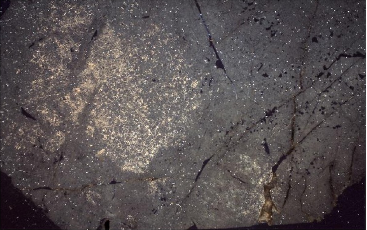
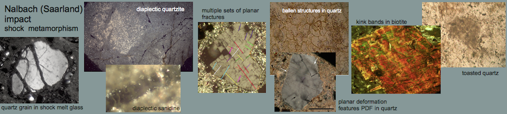
Fig. 17 – 1. Quartzite, practically completely transferred to diaplectic glass, Saarland impact; photomicrograph, crossed polarizers, 48 mm field width. (image Berger 2014)
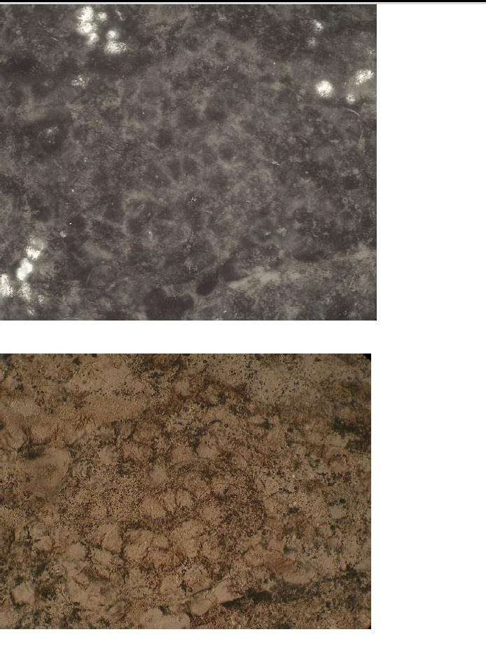
Fig. 17 – 2. Diaplectic quartz grain texture, quartzite, Saarland impact; crossed polarizers (upper) and plane light (lower), 560 µm field width.(image Berger 2014)
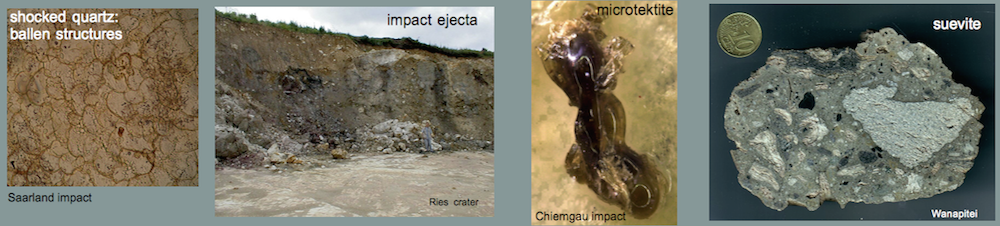
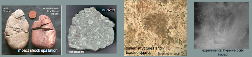
Ballen structures in quartz
Ballen-structured quartz has been interpreted as pseudomorphs after cristobalite which, in turn is thought to have replaced quartz glass quenched from the liquid state. It may also represent recrystallized diaplectic glass or lechatelierite which underwent transition to cristobalite and α-quartz (see e.g., Schuraytz & Dressler, Smith et al., Ferrière et al.).
Ballen structures (Saarland impact)
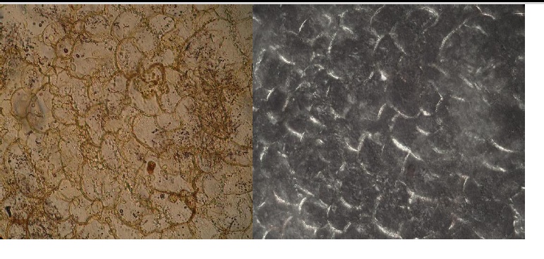
Fig. 17 – 3. Ballen structures, blue impact glas with quartzite particles, Saarland impact; photomicrograph, plane light and crossed polarizers, 560 µm field width.(image Berger 2014)
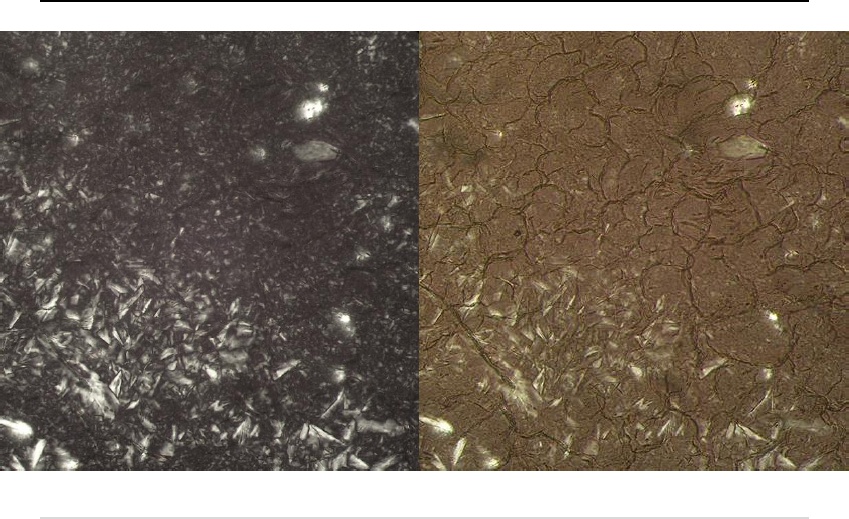
Fig. 17 – 4. Cristobalite passing into tridymite, and ballen structures, shocked quartzite cobble, Saarland impact; photomicrograph, crossed polarizers and slightly rotated (crossed) polarizers, 1.4 mm field width.(image Berger 2014)
Toasted quartz
The orange-brown to grayish-reddish-brown “toasted bread” appearance as a post-shock effect is attributed to tiny vesicles (see, e.g., Ferrière et al.).
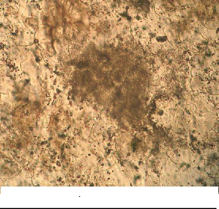 Fig. 17- 5. Toasted quartz with ballen structures, Saarland impact; photomicrograph plane parallel light, 560 µm field width. (image Berger 2014)
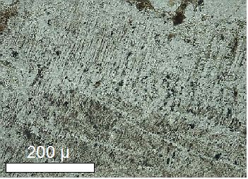
Fig. 17 – 6. Toasted quartz with multiple sets of PDFs, Chiemgau impact.
Mosaicism
Mosaicism is a common feature of plastic deformation of minerals by dynamic compression. Under the microscope it shows as a strongly irregular extinction pattern (mottled extinction pattern) originating from the formation of differently orientated blocks within the crystal structure. Mosaicism is a typical shock effect but may develop also under very high static compression. It has been reported also from the volcanic Toba caldera (Carter & Officer 1989). In general, pressures > 10 GPa are assumed for the formation of mosaicism (Carter & Officer 1989).
 Fig. 18. Quartz grains with strongly mottled extinction pattern (mosaicism). Shocked sandstone, Azuara impact structure, Spain. Photomicrograph, crossed polarizers, field width 800 µm. Photo: G. Mayer.
Planar features
Shock-produced planar features comprise a broad spectrum of deformations in various minerals as are planar deformation features (PDFs), planar fractures (cleavage, PFs), faults, kink bands, twinning and micro-twinning, and deformation lamellae.
Planar deformation features (PDFs)
PDFs in quartz is one of the most convincing shock indicators, and there are lots of studies and analyses (Stöffler 1972, Stöffler & Langenhorst 1994, Grieve et al. 1996, and many others). PDFs are closely spaced (spacing < 1 µm up to the order of 10 µm) and narrow (fractions of µm) isotropic lamellae following crystallographic planes in the crystal. “Isotropic” means PDFs behave optically like a glass. The lamellae may be homogeneous or decorated with tiny inclusions. According to current knowledge, PDFs can be formed under shock deformation only but not in volcanic or tectonic geologic processes. Minimum pressures for the formation of PDFs in quartz are about 5 – 10 GPa (= 50 – 100 kbar). PDFs are common shock features also in feldspar and are rarely observed in other minerals like denser mafic minerals.

Fig. 19. PDFs in quartz; suevite, Nördlinger Ries impact structure, Germany. Crossed polarizers; field width 460 µm.
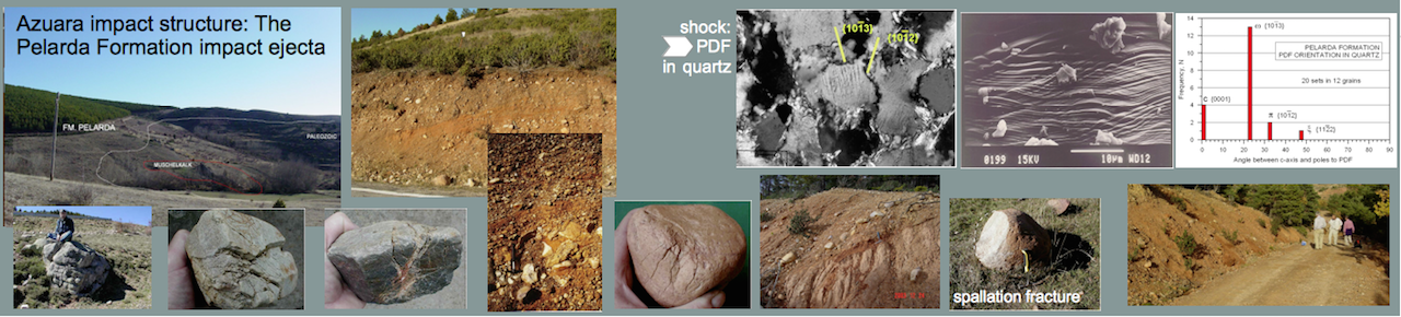
 Fig. 20. SEM image of two sets of crossing planar deformation features in quartz. Quartzite clast from the Pelarda Fm. ejecta, Azuara impact structure, Spain. Note the spacing of the individual PDFs, which is distinctly less than 1 µm in many cases.
-(10-13)")
Fig. 21. Planar deformation features in quartz; quartzite cobble from the Pelarda formation ejecta, Azuara impact structure. The two sets of PDFs represent the {10-12} and {10-13} crystallographic orientations (see histogram in Fig. 28), indicative of high shock pressures > 10 GPa.

Figs. 22. Multiple sets of planar deformation features in quartz. Suevite, Ries impact structure.
 Fig. 23. Multiple sets of planar deformation features in quartz; strongly shocked polymictic breccia, Azuara impact structure.
 Fig. 24. Planar deformation features in quartz grains; strongly shocked polymictic breccia, Azuara impact structure, Spain. These shocked breccia quartz grains were the basis for the PDF analyses performed by Dr. Ann Therriault (see Fig. 28).
 Fig. 25. Planar deformation features (PDFs) in quartz; shocked Cretaceous sandstone, Rubielos de la Cérida impact basin, Spain.
 Fig. 26. Planar deformation features in quartz; shocked sandstone clast, Corbatón, Rubielos de la Cérida impact basin.

Fig. 27. Planar deformation features in shocked quartz; basement granitic rock, Rochechouart impact structure, France.
Crystallographic orientation of planar deformation features (PDFs) in quartz
The crystallographic orientation of PDFs is a basic requirement for a shock origin of these lamellae. Especially the {10-13} and {10-12} planes (see figure below) are considered a clear proof of shock deformation. The orientation can be measured by the aid of the universal stage of the polarization microscope.

Fig. 28. Frequency diagram of crystallographic orientation of planar deformation features (PDFs) in quartz. The diagram has been compiled from data put at our disposal by A. Therriault.
Bent planar deformation features (PDFs) in quartz
The requirement PDFs (planar deformation features) should follow crystallographic planes has led to the basically misleading statement of a few impact researchers (e.g. W.-U. Reimold, Berlin, and C. Koeberl, Vienna) that curved PDFs must be considered of non-impact origin.

Fig. 29. Bent planar deformation features (PDFs) in quartz from the Popigai (Russia) impact structure.

Fig. 30. Bent planar deformation features (PDFs) in quartz from the Charlevoix (Canada) impact structure. (Image source Trepmann and Spray 2004).

Fig. 31. Bent planar deformation features in quartz from the Chiemgau (Germany) impact. Field widths 1.5 mm. The bent PDFs are the result of a plastic crystal lattice deformation logically leading to bending of the PDFs.
A short article that adjusts an obsolete belief of Reimold and Koeberl may be clicked here:
Are bent planar deformation features (PDFs) no PDFs?
Planar deformation features (PDFs) in feldspar

Fig. 32. Twins, multiple sets of PDFs and a few spots of diaplectic glass (maskelynite) in shocked feldspar. Photomicrograph, crossed polarizers. Note the characteristic “ladder” texture” as described by French (1998). Impact melt rock, Chiemgau impact, Tüttensee crater.
Planar deformation features (PDFs) in mica (Saarland impact)
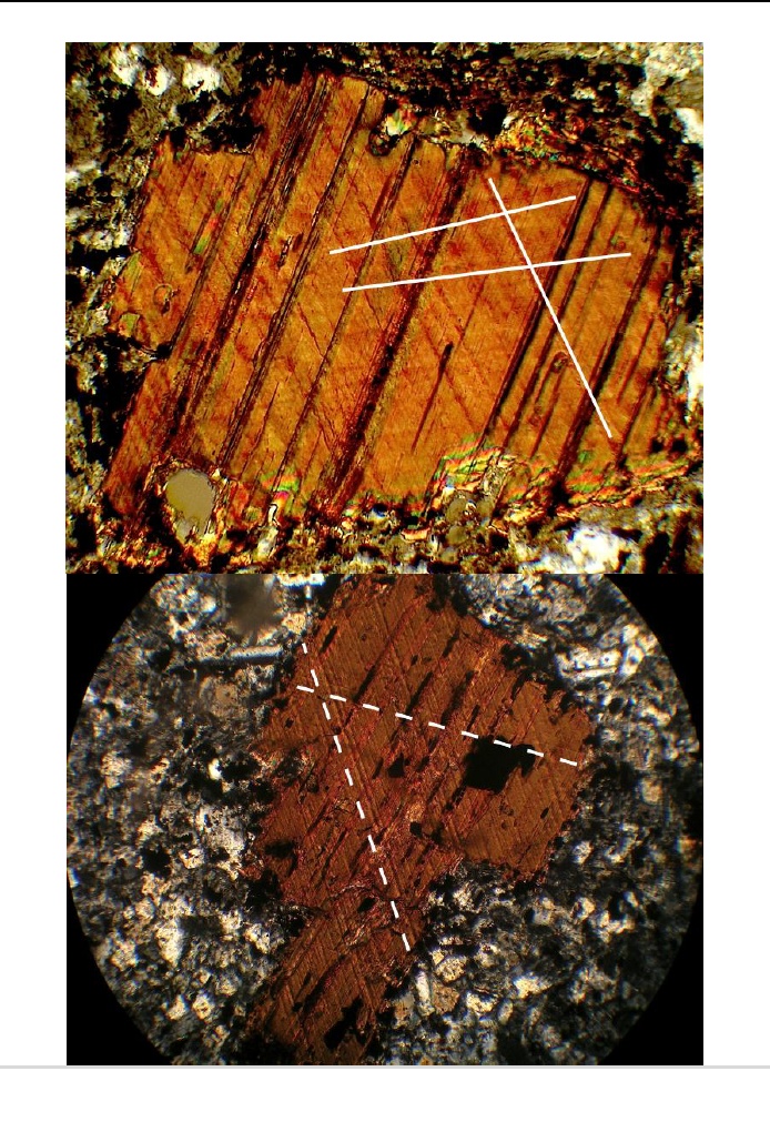 Fig. 32-1. Multiple sets of PDFs in biotite crossing the (001) cleavage; polymictic breccia, Saarland impact; photomicrographs, crossed polarizers, 540 µm (upper) and 1.4 mm filed widths. (image Berger 2014)
Planar fractures (PFs) in quartz
Commonly, quartz does not show cleavage. In rare cases, in rocks having undergone strong regional metamorphism, planar fractures may be developed. In shocked quartz, cleavage is regularly observed.
Planar fractures (Azuara impact structure)

Fig. 33. Photomicrograph (crossed nicols) of planar fractures (cleavage) in quartz typical of shock wave damage, but very uncommon in tectonically deformed quartz. Six sets of different orientation can be observed. Crystallographic planes {10-11} [a], {0001} [b], and {51-61} [c] were determined by universal stage measurements. Strongly shocked polymictic breccia, Azuara (Spain) impact structure. Field width 430 µm.

Fig. 34. Multiple sets of planar fractures (cleavage) in quartz. Shocked Cretaceous (Utrillas) sandstone, Azuara impact structure, Spain. Photomicrograph, crossed polarizers, field width 800 µm. Photo: E. Waasmayer.
Planar fractures (Ries impact crater)

Fig. 35. Photomicrograph (crossed polarizers) of multiple sets of planar fractures in quartz; suevite, Ries (Germany) impact structure. Field width 600 µm.
Planar fractures (Rochechouart impact structure)

Fig. 36. Three sets of planar fractures in quartz; suevite, Montoume variety, Rochechouart (France) impact structure. Photomicrograph, plane light, field width 480 µm. The NE quartz grain displays one set of SW – NE trending planar deformation features.
Planar fractures (Saarland impact)
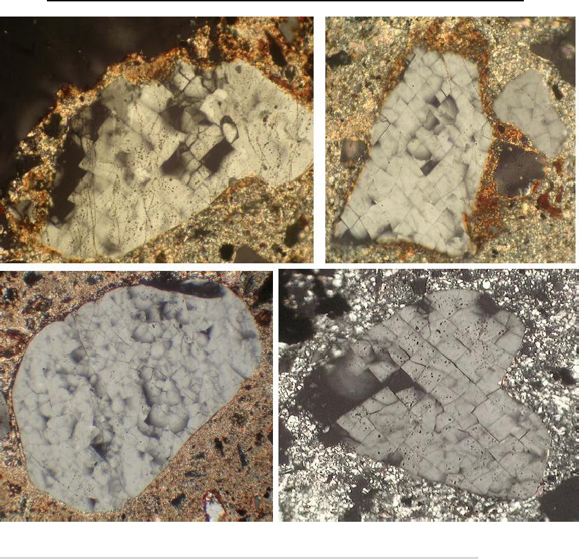 Fig. 36 – 1. Multiple sets of planar fractures (and spots of diaplectic glass) in quartz grains, polymictic breccia, Saarland impact; photomicrographs, crossed polarizers, field widths 560 µm. (image Berger 2014)
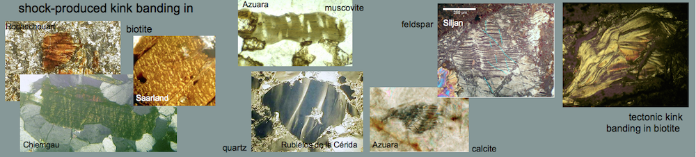
Kink bands
Kink bands are a common shock feature in various minerals and are best known from shocked micas. They result from gliding within the crystal combined with an external axis of rotation. As kink bands are well known also in tectonically deformed micas, they are not diagnostic of shock. A high frequency of the kink bands, narrow widths, and a high kink angle asymmetry may speak in favor of shock deformation (Hörz 1970).
Kink bands in mica
 Fig. 37. Strong kink banding in biotite from a highly shocked polymictic breccia (Azuara impact structure, near Nogueras). Photomicrograph, crossed nicols; the field is 840 µm wide. Although kink bands can be formed under static conditions of strong regional metamorphism, the high frequency of the kink bands shown here, their narrow width, and their high kink angle asymmetry point to shock deformation.
 Fig. 38. Two sets of conjugate closely spaced kink bands in mica. Photomicrograph, crossed polarizers, field width 1 mm. Shocked gneiss cobble, Chiemgau impact (Germany), Tüttensee crater.
 Fig. 39. Distinct kink banding in mica at high angles to cleavage. Gneiss, Chiemgau impact (Germany); photomicrograph, crossed polarizers; field width 650 µm.
 Fig. 40. Kinked biotites. Shocked crystalline rock from the Rochechouart impact structure, France.
 Fig. 41. High frequency of kink bands in muscovite; suevite, Chassenon, Rochechouart impact structure. Photomicrograph, xx polarizers, field is 210 µm wide.
 Fig. 42. Kinked mica, shocked sandstone, Azuara impact structure, Spain. Photomicrograph, crossed polarizers and plane light.
 Fig. 43. High frequency of closely spaced kink bands in biotite. On average the kink-band width is only 10-20 µm. Photomicrograph, crossed polarizers, field width 1.4 mm. – Gneiss cobble, ejecta of the Lake Tüttensee crater, Chiemgau impact.

Fig. 44. For comparison: tectonically deformed mica exhibiting several kink bands. Photomicrograph, crossed polarizers, field width 800 µm. Hydrothermal dike, near Bragança, Portugal.
Kink bands in quartz

Figs. 45-48. Probably shock-produced deformation lamellae and kink banding in quartz. Photomicrographs, crossed polarizers. Shocked sandstones and quartzites, Rubielos de la Cérida (Spain) impact basin. Width of the fields is between 200 and 500 µm.
 Fig. 46. Prominent kink bands in quartz. Rubielos de la Cérida impact basin.

Fig. 47. Kink bands and plastic deformation in quartz. Rubielos de la Cérida impact basin.
 Fig. 48. Kink bands and deformation lamellae in quartz. Buntsandstein sandstone. Rubielos de la Cérida impact basin, Spain.
Kink bands and faults in feldspar and quartz
 Fig. 49. Probably shock-produced faults (dotted lines) and kink banding in feldspar. Photomicrograph, crossed polarizers; suevite, Siljan (Sweden) impact structure.
 Fig. 50. Vitrified fault cutting through quartz grains (pseudotachylite ?) in a strongly shocked polymictic breccia, Azuara impact structure, Spain. Photomicrograph, crossed polarizers.
Micro-twinning in calcite
Deformation twinning in minerals is a common outcome of shock load however not especially significant. In calcite, shock may lead to intense micro-twinning otherwise rarely observed in tectonically deformed calcite.
 Figs. 51-55. Photomicrographs (crossed polarizers) of micro-twinning in calcite from shocked rocks. Fig. 51. Micro-twinning and kink banding in calcite; dike breccia, Azuara (Spain) impact structure; field width 200 µm. Photo: G. Mayer.
 Fig. 52. Multiple sets of micro-twins, polymictic breccia, Rubielos de la Cérida (Spain) impact basin; field width 480 µm.

Fig. 52 A. Multiple sets of planar deformation features (microtwins) in calcite from a polymictic breccia, Rubielos de la Cérida impact basin. The twin spacing and width is about 1 µm. Crossed polarizers.
 Fig. 53. Five sets of closely spaced and partly bent deformation features in calcite. The spacing of the micro-twins (e.g., SW – NE trending) is in part 2 µm only. Calcite dikelet, Chiemgau impact, Tüttensee crater.
 Fig. 54. Strongly deformed calcite exhibiting multiple sets of micro-twins and a few kink bands; calcite dikelet in quartzite, Chiemgau (Germany) impact; field width about 1 mm.
Oxidized biotite as a shock effect
Oxidized biotites are the result of high temperatures (> 600°C) and are known to occur as a shock effect (post-shock temperature) in impact structures at pressures > 45 – 50 GPa. Oxidized biotites may also be related with volcanism.
 Fig. 55. Oxidized biotite with strongly reduced pleochroism. The opaque ribbons are assumed to be magnetite. Photomicrograph, plane light, field width 800 µm. Shocked sandstone. Azuara impact structure, Spain. Photo: G. Mayer.
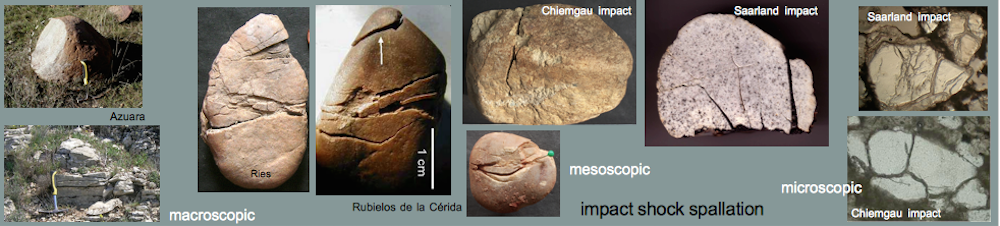
Open spallation fractures in quartz grains as a shock effect
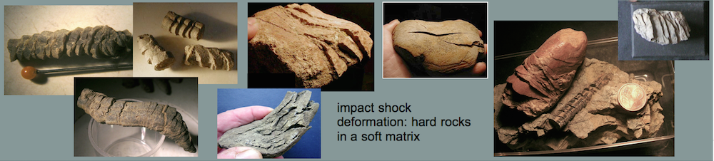
A common (but in general not recognized by impact researchers) shock effect in quartz grains are open spallation fractures that have originated from shock wave reflection at the grain surfaces. Because of the frequently significant impedance difference the compressive shock is reflected as a tensile rarefaction leading to spallation and open, in many cases subparallel tensile fractures. For geometrical reasons the fracture pathway frequently mirrors the shape of the grain boundary. It is obvious that these effects can best be observed in quartz grains embedded in a softer matrix (e.g. sandstones) where the required impedance contrast may be given.
 Fig. 56. Shocked sandstone with subparallel open spallation fractures in quartz grains. The shock front moved from WSW to ENE, or vice versa. Rubielos de la Cérida impact basin. Photomicrograph, crossed polarizers, field width ca. 2.5 mm.
 Fig. 57. More shocked quartz grains in a sandstone sample with distinct subparallel open spallation fractures. Field width ca. 800 µm. Rubielos de la Cérida.
 Fig. 58. More shocked quartz grains in a sandstone sample with subparallel open spallation fractures. Note the large grain (to the right) with the curved open fracture mirroring the grain boundary and see the Fig. 60 with the experimentally produced equivalent. Field width ca. 800 µm. Rubielos de la Cérida.

Fig. 59. Open spallation fractures in quartz filled with impact melt glass. Note the fracture geometry nicely mirroring the grain boundaries. Chiemgau impact (Germany), shocked cobble from the #004 crater. Photomicrographs, crossed polarizers, field width 800 µm each.

Fig. 60. Experimentally produced spallation in quartz spheres; specimen sawed after the shot. Note the lens-shaped spallation fracture as a mirror of the sphere’s surface.
Further reading:
http://www.lpi.usra.edu/publications/books/CB-954/CB-954.intro.html
PDF download of Bevan M. French (1998): Traces of Catastrophe. A Handbook of Shock-Metamorphic Effects in Terrestrial Meteorite Impact Structures. LPI Contribution No. 954, 120 pp.